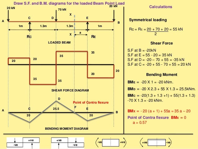

The direction of the jump is the same as the sign of the point load. Shear force and bending moment diagrams are analytical tools used in conjunction with structural analysis to help perform structural design by determining. Hence the value of the shear curve at any axial location along the beam is equal to the negative of the slope of the moment curve at that point, and the value of the moment curve at any point is equal to the negative of the area under the shear curve up to that point. Point loads cause a vertical jump in the shear diagram. A moment balance around the center of the increment givesĪs the increment \(dx\) is reduced to the limit, the term containing the higher-order differential \(dV\ dx\) vanishes in comparison with the others, leaving by Dr Seán Carroll Published: 23rd July 2022 Tutorial In this tutorial we’ll explore the moment distribution method.

#Shear and bending moment diagrams examples how to
The distributed load \(q(x)\) can be taken as constant over the small interval, so the force balance is: In this video the example explains how to draw shear force and bending moment diagram of a cantilever beam method of sections or equations.
#Shear and bending moment diagrams examples free
Another way of developing this is to consider a free body balance on a small increment of length \(dx\) over which the shear and moment changes from \(V\) and \(M\) to \(V + dV\) and \(M + dM\) (see Figure 8). We have already noted in Equation 4.1.3 that the shear curve is the negative integral of the loading curve. These students can learn how to calculate and generate Shear Force and Bending Moment Diagrams and we understand the process of beam analysis can sometimes be. Therefore, the distributed load \(q(x)\) is statically equivalent to a concentrated load of magnitude \(Q\) placed at the centroid of the area under the \(q(x)\) diagram.įigure 8: Relations between distributed loads and internal shear forces and bending moments. Where \(Q = \int q (\xi) d\xi\) is the area.


 0 kommentar(er)
